


Radar sensor glossary: Know more about radar.
Expand your radar sensor knowledge! More on radar terms and definitions.
Our glossary will help you expand your radar sensor knowledge. You will discover important basics, definitions and terms from the world of radar technology and radar sensors. Learn more about radar topics such as resolution, alignment, opening angle, measuring spot, measuring rate, measuring range, measuring precision, measuring accuracy, linearity deviation, radar reflectors and other terms from the world of radar sensors. You can also find more information about radar terms in connection with distance radar sensors in our tutorial on distance measurement with radar.

When measuring distances with radar sensors that have a narrow opening angle (or beamwidth), it is important to align the target object correctly to the sensor. For a target object with a flat surface, it is important to align it as accurately as possible perpendicularly to the radar sensor in order to achieve a strong radar signal. As the surface tilts, the radar signal decreases because part of the radar radiation is no longer reflected back to the radar sensor.

The roughness of the surface plays a certain role: With uneven surfaces, the radar signal is more stable when the surface is tilted because the radar beams are scattered and reflected in different directions. In contrast to laser sensors, radar sensors are therefore well suited for determining the distance to objects with very rough surfaces. You can find more information about aligning radar sensors in our tutorial on distance measurement with radar sensors.
In most cases, radar sensors for collision avoidance are based on FMCW radar technology. These radars can determine the distance to stationary or moving obstacles within the beam of the radar sensor. Falling below defined threshold distances activates a multi-stage security process. In vehicles with radar-based collision avoidance systems, there are usually two safety zones defined by distance values: a warning zone and a protection zone. The warning zone defines a distance at which the vehicle automatically reduces its speed in order to be able to stop in time. The protection zone takes effect within the warning zone when the vehicle is already decelerating. This zone defines a distance at which the vehicle is brought to a standstill to avoid the collision.
Radar sensors have certain advantages compared to other sensor technologies when it comes to avoiding collisions. Powerful radar sensors always provide reliable measurement results even in difficult conditions with large temperature differences, humidity, rain, snow, dust, dirt or smoke. In addition, in contrast to Lidar sensors and camera systems, radars have no moving parts or complex optics. They are therefore more robust and require significantly less maintenance.
Today, radar sensors are used for collision avoidance in many industries to prevent accidents, avoid unplanned downtime and achieve greater productivity. Radar sensors play an important role, particularly in the automotive sector: They are used as parking aids, for distance warning systems, for adaptive cruise control and as cross-traffic alarm systems. But the use of radar sensors for collision avoidance has also become established in other industries such as mining, transport and logistics, robotics and agriculture. Below you will find some application examples for collision avoidance with radar sensors:
Example 1: Collision avoidance for cranes

The radar sensor detects the distance between the two bridge cranes on the crane runway. In order to prevent collisions, the crane speed is gradually reduced in defined distance zones until an emergency stop occurs in the protection zone.
Example 2: Collision avoidance for mining vehicles

Radar sensors can be used to reliably detect obstacles of mining vehicles within defined safety zones to prevent collisions – even in the difficult production environments of mining.
The continuous wave (CW) radar sensor is an unmodulated radar primarily used for speed measurement. In contrast to the FMCW (frequency modulated continuous wave) radar sensor, the CW radar sensor emits radar waves with a constant frequency and amplitude.

- CW radar sensor: no frequency modulation

- FMCW radar sensor: the frequency is modulated

CW radar sensors measure the frequency difference between the transmitted signal and the received signal to determine the so called Doppler frequency. This Doppler effect or shift can be used to calculate the speed of moving objects. CW radar sensors that measure speeds are therefore also called Doppler radars.
The police use CW radars as "speed cameras" in traffic to detect illegal speeding. The continuous wave radar sensor is also used in sports – e. g. in football to measure the ball's velocity when a goal is shot.
Radar sensors are suitable for measuring objects of various types and shapes. Thus, radar technology can be used to determine the height, width, thickness or diameter of plates, rods, pipes and other objects. The typical way to precisely measure objects is using radar sensors for distance measurement based on FMCW radar technology. The FMCW radar sensors emit radar waves that are reflected by the target object. The distance to the target object is calculated by comparing the transmitted and received signals.
To measure the dimension of objects, you need two radar distance sensors. For this purpose, the radar sensors are placed opposite to each other at a precisely known distance. The radar sensors can then measure, for example, a rectangular object from both sides. The sensors are aligned as precisely as possible perpendicularly to the object. The distances measured by both radar sensors are then subtracted from the known distance value. The result is the desired object dimension – be it the object width, height or thickness. Learn more on distance sensor types and the advantages of radar.
Example 1: Width measurement of metal plates
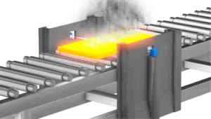
During this object measurement, the radar sensors detect the opposite side edges of the metal plate to measure the width of the steel, copper or aluminum slab.
Example 2: Thickness measurement of steel plates
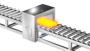
In this example, two radar sensors measure a metal slab from the top and bottom, thereby determining the thickness of the metal plate.
Radar sensors can be used to precisely measure distances to target objects made of any material. Radar sensors for distance measurement are usually based on FMCW (frequency modulated continuous wave) radar technology: FMCW radar sensors emit a radar frequency that steadily increases and/or decreases over a defined frequency band range (e. g. from 122 to 123 GHz). The exact distance can then be calculated from the frequency shift of the transmitted and received signals between the radar and the target object.
Find out more information on distance measurement and sensor types as well as applications of radar distance sensors.
Example 1: Height measurement on the conveyor belt

In this application, the radar sensor is placed above the conveyor belt. The radar sensor then measures the different heights of bulk material on the conveyor belt. The bulk material height can be calculated using the difference between the bulk material distance and the known conveyor belt distance. Depending on the conveyor belt speed, conclusions can be drawn about the bulk material dosage or the conveyor belt throughput.
Example 2: Ground distance measurement
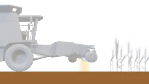
In this application, the radar sensor continuously measures the distance to the ground. The distance values enable a precise height adjustment of the cutting unit or plow.
The frequency modulated continous wave (FMCW) radar technology is the basis for many types of radar sensors. For instance, most radar-based distance sensors are based on FMCW radar technology.

The FMCW radar sensor sends out a radar frequency that is constantly increased or reduced over a precisely defined frequency band. This frequency modulation is called chirp or sweep.
As soon as the radar signal hits an object, the emitted radar waves are reflected and received by the FMCW radar sensor. The frequency of the received signal differs from that of the transmitted radar signal. The exact distance to the target object can ultimately be calculated from the difference between the two signals, the so-called frequency shift.
You will find more information on our FMCW radar page.
Depending on the area of application as well as national or international frequency administrations, radar sensors use different frequency ranges in the microwave spectrum from 1 to 300 GHz. Many of the frequency ranges used by radar sensors are in so-called ISM bands (Industrial, Scientific and Medical bands): This refers to frequency bands that can be used license-free and generally without approval in industrial applications, in research and science, for medical purposes and in domestic applications. In addition, radar sensors in the automotive sector use specific frequency bands, such as the "Automotive Long Range Radar" (LRR) band starting at 76 GHz, the "Automotive Short Range Radar" (SRR) band starting at 77 GHz and various ultra-wide bands (UWB). For radar-based level measurement sensors in the frequency ranges 24-26 GHz and 77-81 GHz (simplified 80 GHz), specific regulatory approval requirements apply depending on the country or region. In Germany, for instance, the regulation for "non-navigational positioning radio for level radars" is applicable. Below you will find the most important frequency bands used by radar sensors:
24 GHz (ISM band)
This ISM band is primarily used for radar sensors in the automotive sector – e. g. for distance warning systems or blind spot detection. The frequency range extends from 24 GHz to 24.25 GHz, which corresponds to a bandwidth of only 250 MHz.
24 GHz (Ultra-wide band for automotive & level measurement)
The ultra-wide band from 24 GHz to 26 GHz (sometimes also from 21 GHz to 26 GHz) was used in the past by radar sensors for automotive applications such as stop-and-go or lane change assistants. However, new regulations in Europe and the USA stipulate that radar sensors for automotive applications should only use the LRR and SRR bands in the range from 76 to 80 GHz in the future. In the past, radar sensors for level measurement have also used the 24 GHz frequency range. Here too, the trend goes towards using the ultra-wide band for level radars from 76 to 80 GHz.
61 GHz (ISM band)
The ISM band from 61 GHz to 61.5 GHz (simplified 60 GHz) is used by radar sensors for industrial applications, among other things. It has a frequency bandwidth of 500 MHz. Depending on the country or region, the regulatory authorities have expanded the frequency range from 57 GHz to 64 GHz (in some cases even up to 71 GHz). This makes frequency bandwidths of 7 GHz and more possible. These extended frequency ranges can be used by so-called MIMO or 3D radar sensors for presence detection, gesture or motion detection in industrial, consumer and mobile phone applications where high resolution is crucial.
76 GHz (Automotive LRR band)
The so-called "Automotive Long Range Radar" (LRR) band is reserved for radar sensor applications in the automotive sector. These include, among other things, adaptive cruise control, cross-traffic alert, blind spot detection and lane change assistance. The frequency band ranges from 76 GHz to 77 GHz and therefore has a frequency bandwidth of 1 GHz.
76 GHz (Ultra-wide band for level measurement)
This ultra-wide band is used by radar sensors to measure fill levels. It usually ranges from 76 GHz to 80 GHz and therefore has a bandwidth of 4 GHz.
77 GHz (Automotive SRR band)
The "Automotive Short Range Radar" (SRR) band ranges from 77 GHz to 81 GHz, which corresponds to a frequency bandwidth of 4 GHz. This ultra-wide band is, among other things, intended as a replacement for the 24 GHz automotive ultra-wide band. Regulation has not yet been completed in all countries and regions.
122 GHz (ISM band)
This ISM band ranges from 122 GHz to 123 GHz and therefore has a frequency bandwidth of 1 GHz. Some regulators have expanded the frequency range from 120 GHz to 123 GHz (sometimes even 116 GHz to 123 GHz), which corresponds to a bandwidth of 3 GHz to 7 GHz. This allows the use of radar sensors for industrial applications with the highest resolution and precision.
Frequency Shift Keying (FSK) radar sensors belong to the category of continuous wave radars – together with FMCW and CW radar sensors. In contrast to pulse radar sensors, all of these radar sensors continuously emit radar waves during the measurement. Just like the FMCW radar sensor, the FSK radar sensor also performs frequency modulation. However, while the radar signal in the FMCW radar increases or decreases continuously over a defined frequency range, the FSK radar constantly switches back and forth between at least two frequency values.

Because the radar signal resembles a rectangle due to the continuous frequency switching, the FSK radar principle is also referred to as “rectangular modulation”. By comparing the phases before and after the frequency switching, the distance to objects can be measured. The Doppler frequency can also be used to determine the speed of a moving object. The FSK radar sensor is used, among other things. in applications where the distance to a moving object needs to be recorded.
Both laser and radar sensors emit electromagnetic waves that are reflected back by the target object and then processed. However, radars transmit radiation in the microwave range, while lasers send out a light signal with a significantly higher frequency. This is why the wavelength, which increases with a lower frequency, is significantly larger for radar sensors than for laser sensors.
This means that fine particles such as dust or raindrops do not prevent the propagation of the radar signal, because its wavelength is in the millimeter range and thus larger than the particles. They do however disturb the laser signal, because its wavelength is in the micrometer range or below. Radar sensors are therefore significantly more suitable for outdoor use or harsh production environments with steam, smoke and dust. Likewise, dirt on the radar lens usually does not affect the measurement result.
Due to the delicate laser diodes, laser sensors are usually more sensitive than radar sensors regarding environmental conditions such as extreme temperatures, vibrations or pressure variations. Even difficult lighting conditions do not influence the radar beams, nor do rough materials or surfaces in certain colors affect the measurement.
Although measurement accuracies in the micrometer range can now be achieved with high-performance radar sensors, triangulation lasers sensors enable even more precise results in limited measurement ranges, if certain environmental conditions are provided.
Below you will find a comparison of the performances of radar sensors, ultrasonic and laser sensors:
Sensor performance | Radar 122 GHz | Ultrasonic ToF | Laser ToF | Laser Triangul. |
Measuring with dust, dirt, smoke, fog, water drops, snow | 3/3
| 2/3
| 1/3
| 1/3
|
Robustness against vibrations, extreme temperatures, difficult light conditions, pressure variations | 3/3
| 1/3
| 1/3
| 1/3
|
Measuring through plastic, glas etc. | 3/3
| 2/3
| 1/3
| 1/3
|
Accurate distance measurement | 3/3
| 1/3
| 2/3
| 3/3
|
Wide measuring range | 3/3
| 1/3
| 3/3
| 1/3
|
Measuring tilted object surfaces (non-perpendicular) | 2/3
| 2/3
| 3/3
| 3/3
|
Acquisition costs | 2/3
| 3/3
| 2/3
| 1/3
|
Low-maintenance sensor | 3/3
| 2/3
| 1/3
| 1/3
|
Radar sensors are now widely used in level measurement. While pulse radar sensors were used for level measurement in the past, FMCW radar sensors (24 GHz, 80 GHz und 122 GHz) have now become established. Because radar sensors measure contact-free, they are ideal for checking the level of aggressive solids and corrosive liquids or when hygiene requirements are particularly high, such as e. g. in the food or pharmaceutical industry. In addition, radar sensors can also measure the fill levels through silo, tank or vessel walls if the wall material is not metallic or conductive. This means that there is no contact between the radar sensor and the measured medium. This may be required in the chemical and pharmaceutical industry. Another advantage: High-performance radar sensors deliver reliable measurement results even in harsh environments. Extreme temperatures, pressure differences, humidity, dust, dirt, steam and smoke typically have no influence on the level measurement. This also applies also to dirt or water droplets on the lens.
When measuring filling levels, the radar sensor is usually mounted vertically above the measured medium. The emitted radar waves are completely or partially reflected by the liquid or solid (e.g. bulk material or powder) and received by the radar sensor. The exact filling level is then calculated from the determined distance value based on the total filling height of the container. If the level measurement is carried out in a container, radar sensors with a small opening angle usually offer better measurement results. Measurement errors that can occur due to interfering reflections on the wall can thereby be avoided.
Radar sensors are suitable for measuring the level of powder, bulk solids, liquids or pastes in silos, process and storage tanks or other containers. Level measurement radar sensors are used, among other things, in the food industry, in the chemical and pharmaceutical sectors, in the cement and building materials industry, in the metal industry and in mining.
Find out more information on fill level measurement and level sensor types as well as applications of radar level sensors.
Example: Level measurement of molten metal
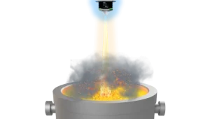
To measure the level of hot, liquid metal, high-performance radar sensors are required that can reliably measure through dust, steam and smoke even at metal temperatures of up to 1600 degrees Celsius. OndoSense radar sensors can be used for the level control in melting furnaces and crucibles, in launder systems, in steel ladles, ladle cars and casting molds as well as in direct chill (DC) or die casting of slabs.

The linearity deviation indicates the greatest possible deviation between the ideal value and the value determined by the measuring system within a defined measuring range. For example, if a radar sensor with a linearity deviation of 0.1 mm displays a measured distance value of 200mm, then the real distance value is in the range of 199.9 to 200.1 mm. The smaller the linearity of a measuring system, the better its measuring performance. The linearity is usually defined as ±00% of the final value. When determining linearity, measurement fluctuations due to remission degree, temperature or switch-on drift and other criteria are usually not taken into account.
Measurement accuracy is an important quality factor for radar sensors for distance measurement. The JCGM (Joint Committee for Guides in Metrology) defines accuracy in the International Vocabulary of Metrology (VIM 2012 edition) as the "the closeness of agreement between a measured quantity value and the true quantity value of a measurand".

Accordingly, accuracy in measurement technology is the result of measurement precision and measurement trueness: High measurement precision (outdated: measurement repeatability) exists when the most consistent measurement values possible can be achieved through repeated measurements under constant conditions. However, high measurement trueness is achieved when the average of a large number of measured values corresponds to an ideal reference value.
A radar sensor or other measuring system is therefore accurate if it repeatedly delivers precise measurement values and always achieves correct measurement values on average.
High measurement precision (outdated: measurement repeatability) means that a measuring device (e. g. a radar sensor) achieves the most consistent measurement values possible in repeated measurements under constant conditions. In metrology (measurement technology), measurement precision is the basis for measurement accuracy in conjunction with measurement trueness. You can find more information under "measurement accuracy".
The measuring range (or reach) of a radar sensor refers to the spatial dimension in which the sensor can successfully detect a target object based on its technical specifications. The measuring range is usually specified with the smallest possible measuring distance and the largest possible measuring distance in meters or millimeters (e.g. measuring range: 0.1 to 40 meters). A measurement is only possible if the target object is within these two distance values.
The area between the zero point and the minimum measuring distance is called the blind zone. For a measuring range of 0.1 to 40 meters, the blind zone is <0.1 meter. If there are objects in the blind zone, the radar sensor cannot detect them or can only detect them unreliably. In general, the maximum measuring distance for radar sensors depends on the radar cross section.
In contrast to FMCW radar sensors, pulse radar sensors can achieve ranges of well over 100 kilometers. However, this requires very powerful radar devices, which are normally only used in the military sector or for flight control.
The measurement rate of a radar sensor or a measuring device describes the number of measurements in a certain period of time or the frequency with which the measurement result is updated. It is also referred to as measuring frequency or measuring speed. The measurement rate is usually given in Hertz (Hz) (measurements per second). In addition to the measurement rate, there is also the sampling or output rate. However, this does not refer to how “fast” a measuring device can actually measure, but rather to the frequency with which the interface updates the output signal.
The measuring spot of a radar sensor is determined by the opening angle of the radar lens and influences the precise detection of the target object. The size of the measuring spot can be easily calculated and is an important performance factor for distance measurement. Basically, a large opening angle (beamwidth) results in a large measuring spot, while a small opening angle results in a small measuring spot. For accurate distance measurements, a measuring spot that is as small as possible is beneficial because it leads to a stronger receiving signal with fewer interfering reflections.

Please find more information about the measuring spot in our tutorial for distance measurements with radar sensors. You can also determine the measuring spot of your radar sensor using our spot size calculator.
High measurement trueness exists when the average of a large number of measured values corresponds to an ideal reference value. In metrology (measurement technology), measurement trueness, together with measurement precision, is the basis for measurement accuracy. You can find more information under "measurement accuracy".
MIMO radar sensors are based on a novel FMCW radar technology with multiple transmitter and receiver antennas – hence the name MIMO, which stands for "Multiple Input Multiple Output". With the MIMO radar sensor, each transmitting antenna emits a signal independently of the other antennas, which is picked up by all receiver antennas.

Due to the multiple transmitting and receiving antennas as well as the large antenna area (aperture), MIMO radar technology offers increased horizontal (azimuth) and vertical (elevation) angular resolution compared to classic FMCW radars. This enables the MIMO radar sensor to determine several objects simultaneously in three-dimensional space. To do this, the radar sensor records the horizontal and vertical object angle and thus determines the object position in 3D.
With MIMO technology, radar sensors can distinguish several objects simultaneously not only according to their vertical (1) and horizontal (2) angular position, but also according to their speed (3) and distance (4). Therefore, these MIMO radars are also called 4D radar sensors. With the help of micro-Doppler algorithms, the MIMO radar can detect the smallest human movements – e.g. the up and down movement of the chest when breathing. In addition, the radar sensor can distinguish between human and non-human target objects. Basically, MIMO radar sensors are based on the principle of frequency-modulated continuous wave (FMCW) radar, but MIMO radar measure significantly less precisely and are less stable in complex environments than classic FMCW radar sensors. In addition, the angular resolution is rather low in comparison to Lidar sensors.
The application scope for MIMO radar sensors ranges from counting people and vehicles in public spaces (Smart City), health monitoring of seniors and patients (Smart Health) to collaborative robots in manufacturing and safety sensors for mobile robots in transport and logistics. As a result, collision avoidance can be implemented with MIMO radar sensors – e. g. to identify obstacles that lie on the ground or protrude into the vehicle path from above.
Radar sensors are well suited for object detection of static and moving objects. Based on FMCW radar technology, radar sensors for object detection determine the distance and, if necessary, the speed of the target objects. As a result, these radar sensors are suitable (e. g.) for vehicle counting of trains, height and passage control of trucks, non-destructive presence control of objects in packaging, as well as for position control of cranes or collision avoidance of mining vehicles or agricultural machinery.
While high accuracy plays a minor role in object detection, reliable detection of target objects is of great importance, even in difficult conditions or outdoors. Radar sensors are very suitable in this context because they deliver reliable results even in harsh environments or outdoor areas with extreme temperature fluctuations, rain, snow, dust, dirt or smoke.
Example 1: Position control of cranes or crane booms

Radar sensors record the position of the crane boom or other moving crane components and thus enable reliable position control of cranes.
Example 2: Collision avoidance of mining vehicles
Radar sensors always reliably detect obstacles within defined safety zones, even in the difficult mining production environment, so that the dump truck, excavator or wheel loader can be stopped immediately.
The opening angle (or beam width) is an important parameter in radar technology: It provides information about how large the area is in which objects are detected by the radar beams. The opening angle is calculated using the so-called full width at half maximum (FWHM) of the antenna power of the radar sensor. This is done by determining the maximum antenna performance under almost reflection-free conditions.

The full width at half maximum is then calculated from the angle between the two points in the power curve (radar lobe) of the radar antenna at which the maximum power has fallen to exactly half. The logarithmic scale is usually chosen in such performance curves. For the factor 0.5, this corresponds to the value -3 dB.
In principle, radar sensors with a small opening angle are better suited for highly accurate distance measurement because the radar signal is stronger and there are fewer potential disturbing reflections. In contrast, radar sensors with a large opening angle are usually better suited for collision avoidance because they can detect more potential obstacles. You can find additional information about the opening angle and measuring spot in our tutorial for distance measurements with radar sensors.

A pulse radar sensor emits short pulses at regular intervals that are reflected by objects and received by the radar. In contrast to the FMCW radar sensor, the pulse radar sensor does not continuously emit radar signals. The distance of the objects can be calculated from the the time lag between the emission and reception of the pulses.
Because pulse radar sensors usually work with high transmission power, they can detect objects even at great distances of more than 100 km with an accuracy of up to <20 m. Pulse radars are particularly deployed in the military sector, but are also used for air traffic control, weather observation and earth exploration via satellites. In the past, pulse radar sensors were also used as level radar sensors. FMCW radar sensors have now replaced pulse radars in this application area.
Radar reflectors are used to reflect radar waves as precisely as possible back to the radar sensor, regardless of the direction of incidence. They are also called corner cubes and are made of three surfaces that are arranged perpendicularly to each other.

Radar reflectors help extend the maximum measurement distance. The reason for this is that the increased radar cross section of the reflector significantly amplifies the radar signal. Corner cubes can also increase the angular stability and the accuracy of certain measurements. You can find more information about radar reflectors in our tutorial for distance measurements with radar sensors.
There are two different types of resolution for radar sensors: range resolution and angular resolution. With range resolution, two target objects are distinguished based on their distance to the sensor. This resolution describes the smallest possible distance at which the radar sensor can still distinguish two objects from each other in the radar beamwidth (or opening angle). If the distance between these two objects is less than the resolution of the radar sensor, the objects can no longer be differentiated. The result: The two target objects merge into a single object in the measurement result.

Angular resolution means that two objects are separated based on the side angle and the minimum distance between the objects. For more information about the resolution of radar sensors, read our tutorial on distance measurement with radar sensors.
The "Synthetic Aperture Radar" (SAR) is an imaging radar sensor that is used for earth exploration in aircrafts or satellites. It provides high-resolution two-dimensional images of the earth's surface. The SAR radar sensor uses the trajectory of satellites or aircraft to simulate a huge antenna area. This synthetic aperture works as follows: The SAR radar repeatedly captures a target area on Earth over a longer period of time over the course of its flight path, with the viewing angle constantly changing. The received radar data is then processed together with the precise position data of the flying object. The result is a radar image with a very high resolution.
Because SAR images are similar to photographs and provide good images in almost all weather conditions, including at night, they are often used for mapping, exploring and reconnaissance of the Earth's surface. SAR radar images can achieve reconnaissance of up to 0.1 meters under ideal conditions.
What are the differences between radar sensors and ultrasonic sensors? In contrast to radar sensors, ultrasonic sensors do not emit electromagnetic waves, but rather "mechanical" sound waves. Not only are these significantly slower than radar waves, which travel almost at the speed of light, they also need a medium in which to propagate. The propagation speed of ultrasonic waves varies greatly with the propagation medium. Ultrasound travels at around 330 meters per second in air, but at ten times this speed in bones (3300 meters per second). The speed of sound waves is also highly dependent on factors such as temperature, pressure or humidity. As a result, reliable measurements in adverse environments or outdoors can be difficult. Dirt on the ultrasonic sensor also affects the measurement quality and accuracy.
Radar sensors, on the other hand, always measure reliably even outdoors or in difficult production conditions with extreme temperatures, vibrations, steam, smoke, pressure or dust. Dust or dirt on the lens usually does not have a significant influence on the measurement result.
Below you will find a comparison of the performances of radar sensors, ultrasonic and laser sensors:
Sensor performance | Radar 122 GHz | Ultrasonic ToF | Laser ToF | Laser Triangul. |
Measuring with dust, dirt, smoke, fog, water drops, snow | 3/3
| 2/3
| 1/3
| 1/3
|
Robustness against vibrations, extreme temperatures, difficult light conditions, pressure variations | 3/3
| 1/3
| 1/3
| 1/3
|
Measuring through plastic, glas etc. | 3/3
| 2/3
| 1/3
| 1/3
|
Accurate distance measurement | 3/3
| 1/3
| 2/3
| 3/3
|
Wide measuring range | 3/3
| 1/3
| 3/3
| 1/3
|
Measuring tilted object surfaces (non-perpendicular) | 2/3
| 2/3
| 3/3
| 3/3
|
Acquisition costs | 2/3
| 3/3
| 2/3
| 1/3
|
Low-maintenance sensor | 3/3
| 2/3
| 1/3
| 1/3
|


Smart radar sensor for distance measurements.
OndoSense reach. Compact. Reliable. Outdoor-proof.

High-precision radar distance sensor.
OndoSense apex. Ultra-precise. Fast measurements. Very robust.

Your inquiry on our industrial radar sensors.
Please contact us now for advice & quotes.
You are interested in our industrial radar sensor technology for distance measurement, level measurement, positioning and collision avoidance? Any further questions? The OndoSense team will provide you with answers, advise you on the use of radar sensors in your industrial environment and send you a quote.